Components and Circuits: RC Plane Post 2
- Nov 1, 2019
- 3 min read
RC Plane Post by Hassan Bajwa and Joel Runevic
Introduction
If you haven’t seen the first post on our remote-controlled (RC) plane project, then please check that out first! This is the second post where we explain the subsequent decisions we had to make, in regards to finding components and starting the construction process.
Components and Circuits
We followed this with a series of other component and material decisions, ranging from the transmitter and receiver
model (the FlySky FS-i6) to the 0.2mm balsa wood sheets that we would use to cover the wing struts. A comprehensive list of parts and materials is available upon request.
Talking of wing struts, we came up with a problem. What material and design would we use to translate a clark Y aerofoil shape to a wing? Our initial suggestion was to laser cut repeat Clark Y shapes and cover them with some material, later decided to be sheets of balsa wood, which can be curved to any reasonable shape. However, research conducted by one member suggested that the strength/weight ratio for MDF was too low to execute its purpose - in other words, our wings would be too weak and we would run the risk of encountering a rupture during flight. By a turn of fate, one of our members had access to a 3D printer and was experienced with the operation of the machine. We entrusted him with the task of designing and printing both our tail and wing ribs & control surfaces.
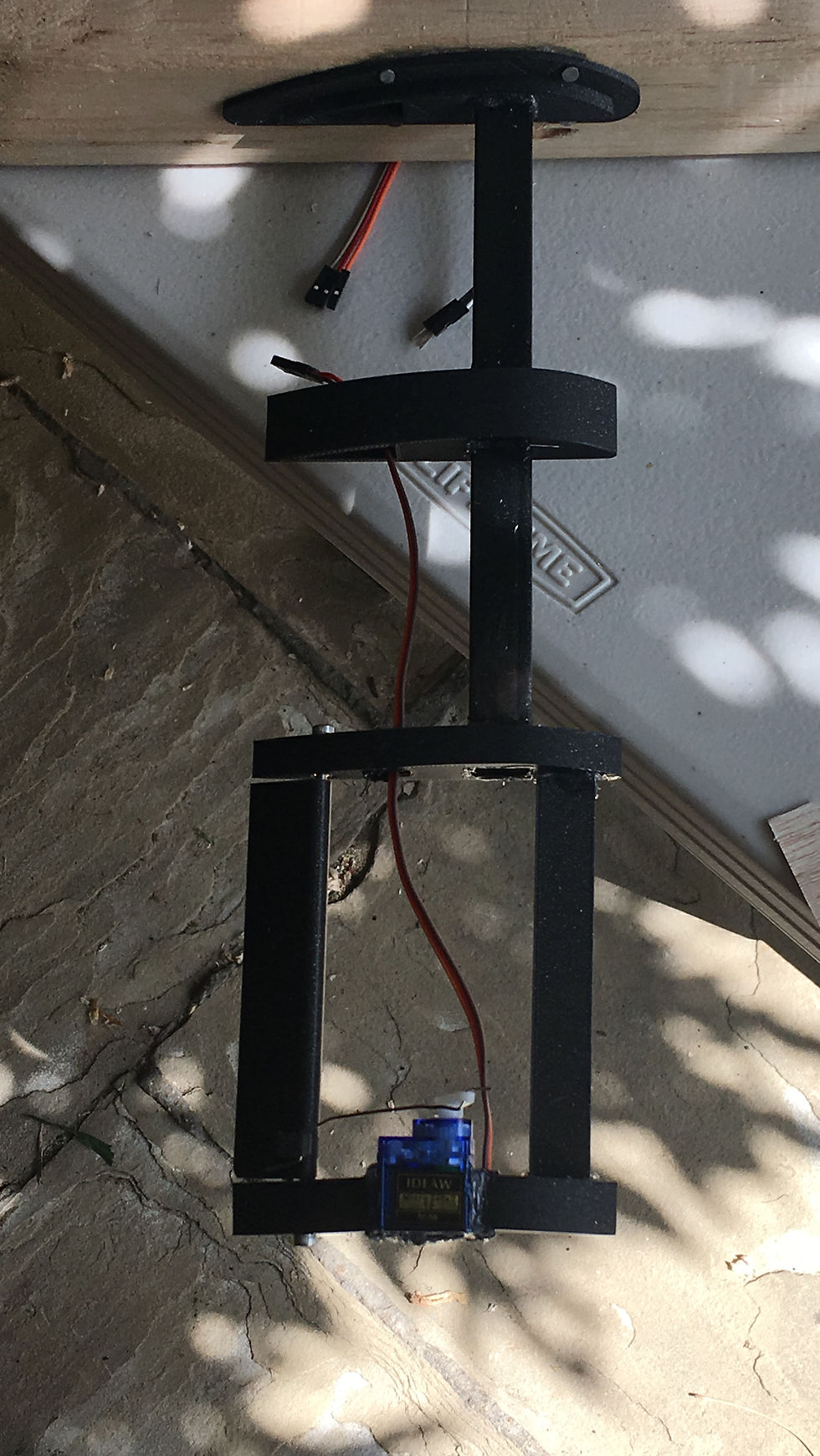
Pictured below are some images of our wing and tail section design.

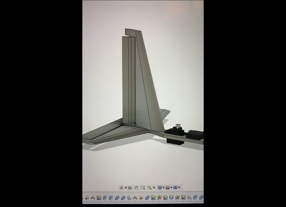

You may have noticed that we only have one flap on each wing in our design - these are known as flaperons and are found in simple aircraft designs such as RC planes. These act opposite to each other - if one rises, the other one will drop. The aim of this is to allow the aeroplane to roll along the Z axis, and to initiate a turn, the aircraft should be rolled along the X axis (i.e. the elevators should be raised). More on this later.
Once we had acquired all the necessary parts, we were faced with the challenge of building our plane and configuring our electrical components, a complicated affair considering we had the bare minimum of experience with the nitty-gritty of remote control electronics. However, one member’s expertise in the area of electronics and mechanics gave us a solid base from which to develop our ability.
To aid us with the electronics, we decided to create an initial circuit diagram - admittedly, it didn’t follow the standard format, but gave us a higher level of clarity when creating our circuit, so it achieved its purpose - we aren’t complaining. We later revised our circuit diagram and will include this in a later post.
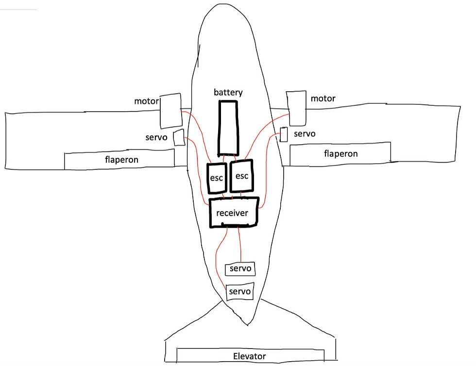
One oversight we made with our original concept of a twin-propeller plane was that we were essentially jumping in the deep end of remote control electronics - as you can see, they can become much more complex with two motors, and the effects on voltage and current requirements made finding a suitable LiPo battery much more difficult. Nevertheless, we managed it in the end, and for the size aircraft we settled on, one propeller would have arguably created more problems than it would have solved.
And that's a wrap for our second post! If you have any further questions, ask them in the comment section. Next time we'll look at our building process, so stay tuned for that!


Comments