Motoring On: Building an RC Plane Post 4
- Rahul Jindal

- Nov 12, 2019
- 9 min read
RC Plane Post 4 by Joel Runevic, Hassan Bajwa and Rahul Jindal
Introduction:
The fourth part in our six part RC Plane series looks at the final building of our plane, focusing on the wings, components and final testing. As always, we recommend reading the other parts in the series instead of just jumping in halfway through (you lazy sod!).
Motoring On:
T - 2 DAYS:
We designed our wings using Fusion 360, the same application we used for the tail section, as our aim was to 3D print 8 struts (4 per wing) and connecting rods to form a structure of Clark Y aerofoil cross section that we would then cover with a 0.05mm balsa wood to form a solid shape. The wing design is shown below, with a wing mount on the left, used to further secure the wing to the fuselage, and a motor mount on the right (the first strut of three), designed in the same configuration as we used in the actual plane. To the right of the motor mount would be a standard strut (the same as the motor mount strut, just without - well, the motor mount), followed by a servo mount strut, which had a hole the same shape as our servos, allowing one to be glued or bolted in to control our flaperons, shown in the second photo.

For strength, we used a hollow aluminium rod of rectangular cross-section to connect the first, second and third y axis struts (y-struts for short) on both wings. This meant we needed to put the rod through the upper fuselage, so an equal amount protruded from each side, as shown. To do this, we drilled a hole in the plane of radius equal to the smaller cross sectional length of the rod (as it was a rectangle).

We also printed connectors for our two outer y-struts, which I shall call x-struts from here on. We needed these as the metal rod could not reach further than the third y-strut, and reducing our wingspan was not an option as we wanted to maximise our lift (there is a positive relationship between wing area and lift generated). The x-struts were fairly simple, fitting into a common hole in the two struts. Additionally, we printed the flaperons, which were bolted loosely (to allow the control surface to move) in between the same y-struts. However, one point to note (bear this in mind for later) is that the strength of the outer struts was going to be severely less than the inner ones as there was a major lack of strong support for them. One wing fully built (note that it is without a balsa wood covering) is shown in the photo.
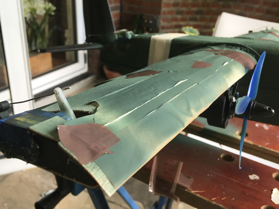
Once we had glued the struts into their positions, we were able to place the balsa wood on our wings. We traced the bottom wing shape onto a sheet of 0.05mm balsa wood, leaving a gap for the flaperon to operate and cutting holes for motor and servo wires to run through. Then, we cut and glued this shape onto the struts, resulting in the image shown below.


The upper half of the wing was slightly more intricate, requiring the same process, but with the wetting of one specific side of the balsa wood to bend it (the wood bent towards the dry side, so it’s as if you were wetting the bottom of a positive co-efficient x^2 graph), which allowed the wood to follow the Clark Y aerofoil shape. However, we executed it with only minor damages (small cracks in the wood easily fixed by masking tape), and we were ready to fit our components!

T - 24 HOURS:
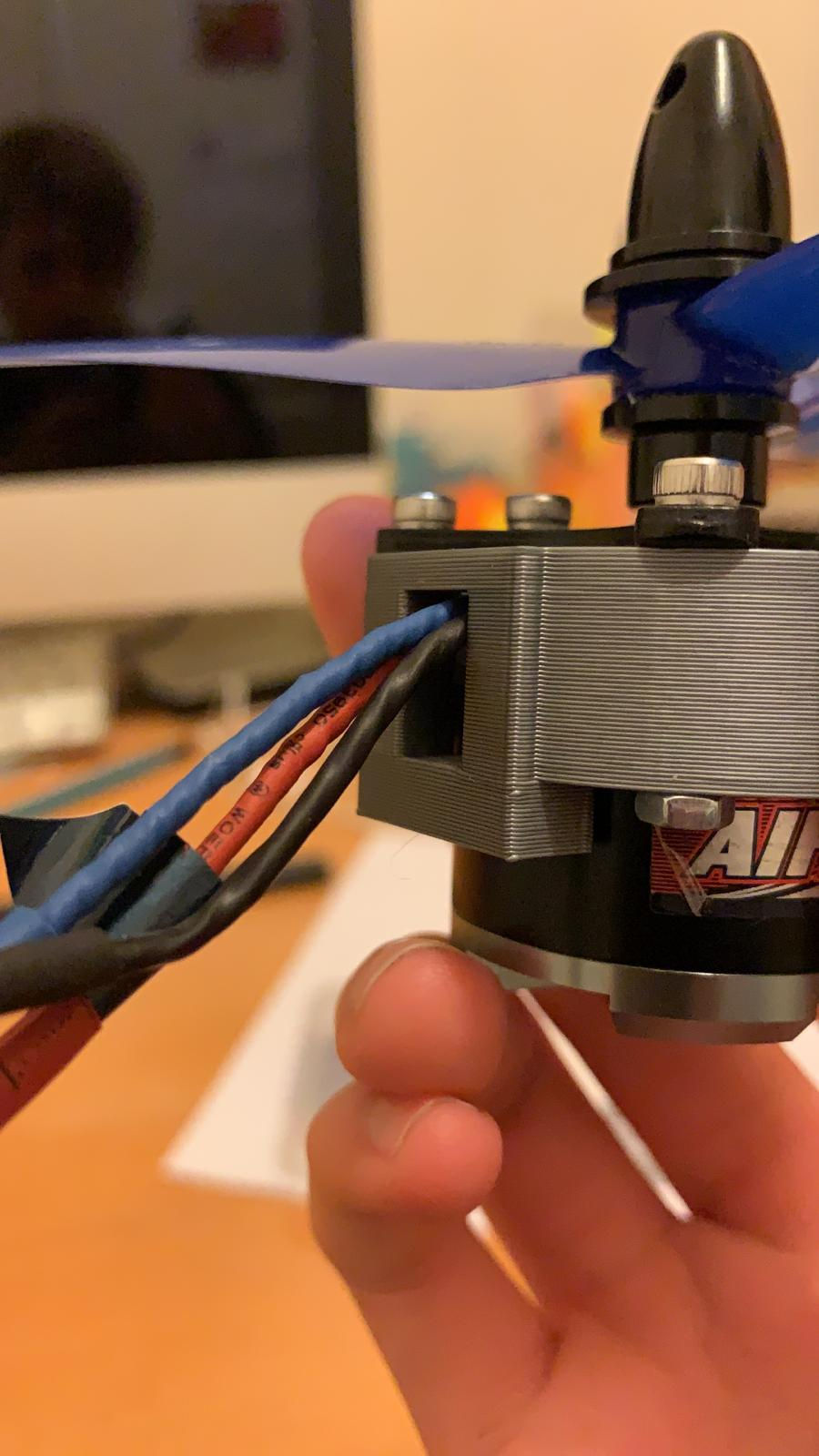
We began by mounting the motors to each wing, this simply required 22mm long bolts to be used which would thread directly into each of the four corners of the motors. This firmly locked them in place so that the motor shaft was perpendicular to the wing which would make sure the line of thrust acts directly forwards. Then we mounted each propellor, and because the diameter of the hole was slightly smaller than the diameter of the motor shaft we decided to use a 5mm drill bit to enlarge the hole ensuring a secure fit on the motor shaft. The motor also came with propeller clips which would be attached firmly onto the shaft of the motor whilst gripping tight onto the propellor. This would allow the motor and propellor to rotate perfectly in sync as well as enable the propellers to be quickly swapped out if needed.
Next we decided to mount the four servos in place starting with the two servos used for each flap. This proved to be slightly challenging as the servo mount was just too small to allow the servo to sit comfortably within the wing. However, after brainstorming a few ideas we came up with a quick and easy solution of using a soldering iron to melt some of the plastic which made sufficient space for each servo to be mounted firmly and flush with the surface of the wings. When wiring the servos directly into the receiver, we found that the wires which came with the servos weren’t of sufficient length which meant that we had to use extension wires. These were simple attachments which extended the cables significantly allowing the servos to be easily connected into the receiver.
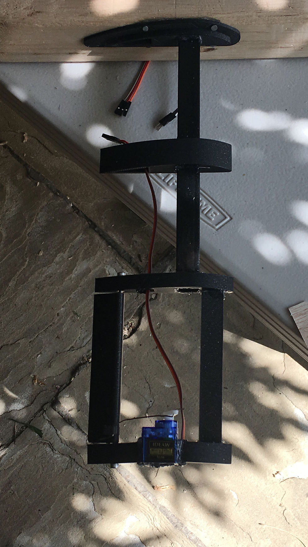
Next we had to create push rods to allow each servo to control the flaps. Due to the price of push rods being surprisingly high for a piece of metal, we came up with the idea of using pliers to bend a paperclip into the desired shape. This was slightly fiddly but worked just as well as regular push rods do, with the advantage of full control over the length of the rod. We aimed to get the flaps as horizontal as possible, but this didn’t matter too much as we knew we could use sub-trim via the transmitter to adjust them perfectly. Once this was done, we mounted the two servos for the rudder (used to control yaw) and the elevator (used to control pitch). To attach each servo flush with the surface of the balsa wood we cut the shape for them and glued them in place with super glue. The servo for the rudder was mounted in an upright position as this meant that the servo arm would rotate following the same axis as the rudder. This meant that less strain would be put on the push rod allowing it to last longer in flight. The same goes for the servo used to control the elevator, this was mounted in a horizontal position as the arm would then rotate along the same axis as the elevator would. This leads to less of a bend in the push rod and a better movement of the elevator. Due to the distance between the servo arm and the control surface being large for both the rudder and elevator, we decided to solder two paper clips together as well as tape them to make sure there is no bend. This worked as well as we hoped and enabled the rudder and elevator to perform their key functions.

Next we worked on arranging the order of the components within the fuselage. We decided to place the battery at the front, ESCs in the middle and receiver at the back. This prevented our plane from being tail heavy which is beneficial when in flight. For the antennae of the receiver we had to ensure there would always be a good connection with the transmitter. To achieve this, we cut a small hole through the back of the fuselage which we used to wire the antennae through perpendicular to each other so the radio waves can be picked up when the transmitter is in any orientation. We decided to mount the ESCs in the middle as they would then be next to the motors which was important as the cables running from each motor weren’t very long. Each ESC was connected to the battery using a Y connector which enabled power to be diverted equally towards them. We made this connector using some high gauge wire to withstand large currents as well as an XT60 connector to connect it directly into the battery. In order to connect the battery into the ESCs we made a channel for the cable to run through located on the bottom of the inside section we cut out. However, we soon realised that separating the fuselage to connect up the cables was a time consuming process where we would need to always have tape at hand to line up each piece and firmly put them together.

Lastly, when all the circuitry had been wired up we decided to mount some landing gear. We went with the formation of having one wheel up front and two at the back which ultimately made the plane look more realistic as well as assisting with take off and landing. In order to mount the wheels we did have a couple issues leveling it out correctly which led to the plane taxiing at a slight angle. However, this was unimportant as we were likely to hand launch it anyway due to the take off sight being slightly grassy. To assemble the landing gear we used screws and PVA glue to ensure a secure fit. However, we did encounter an issue with the front landing gear rotating unnecessarily which was adjusted by using a small screw to lock it in place. Once we addressed this issue, we had completed the assembly of the landing gear and the placement of all the components within the aircraft.

T - 8 HOURS:
Subsequent to the construction of our aircraft, we noticed that the right wing was slightly curved under its own weight due to the end strut being unsupported. More importantly, the wing was not rigid and was thus susceptible to movement. Our fear was that when the plane would be in flight and potentially exposed to strong winds, the frequent movement of the wing may cause damage to the internal structure of the wing. Crucially, the flex of the wing was at the same place as our flaperon, meaning our starboard flaperon would have a greatly reduced effect on the behaviour of the plane, instead focusing more on the weak wing-end. In order to solve this problem, we used part of a wooden skewer as an x-strut in order to strengthen the internal structure of the wing and to maintain shape, soldering holes in the plastic for it and then jamming it in, using the tension in the skewer to maintain a fixed shape.


In addition to this, we tested that our flaps, rudder and elevator were working as required - which, they fortunately did, with the exception of the flap on the left wing. The servo, which is responsible for changing the attitude of the control surface, was rigid and did not allow for full movement of the flap. We tried using the remote control to trim the flap, however it was offset by a greater amount than the maximum trim that the controller would allow us to implement, meaning we were not able to neutralise the flaperon. Upon further inspection, we realised that the servo was broken and thus had to be replaced. Furthermore, when we tested the propellers, we found that one propellor was spinning in the opposite direction to its configuration (the attitude of its blades), resulting in a thrust being generated that would oppose the aircraft’s motion. This wing was performing reverse thrust when it should have been generating standard thrust. This was solved through a simple rewiring of the circuit (we switched the positive and negative terminals around, which were connected to the motor responsible for rotating the propeller), causing the motor to spin in the other direction. Moreover, we tested the landing gear, which provided ample suspension and we deemed the gear satisfactory.
A few days later, when we were approaching the flight date, we ran the plane along a concrete path and noticed that it veered to the port side while taxiing. We considered this as a negligible issue as it is a known tendency in some conventional aircraft (due to uneven weight distribution) and, more significantly, we intended to hand-launch the model, due to the high friction on the grass “runway” we had chosen to at least land the plane on. In order to allow for more efficient testing, we changed the mechanism in which we charged our battery. Previously, we had to take out all the components in order to disconnect and reconnect the battery, which was very time-consuming. Consequently, we cut a hole in the lower fuselage that was parallel to the main cable for the LiPo, which allowed easy disconnecting and charging without having to remove any components. This hole was then covered by a small piece of tape to ensure it doesn’t have a major impact on aerodynamics. After all of this, we were finished with the testing of our aircraft and were ready for flight!
T - 4 HOURS:
The last thing to do before the flight was to prepare - we charged the battery fully, painted the plane (we had some time to kill), sellotaped the fuselage halves together (we wrapped tape around the plane nose and rear several times for security), organised our roles and tested everything one final time.
I was the designated pilot, who would control the plane’s every movement beyond takeoff, the responsibility of Rahul, who would handlaunch the plane. All of this would be filmed on a phone by Joel, and Rahul was then going to video the flight with a drone. We were ready to go.

Conclusion:
And that's it for today! The next post will focus on the flights and fate of the remote control plane, and we’ll analyse its behaviour and evaluate our decision making and building processes. See you next time!


Comments