The Two Slits That Changed Everything
- Apr 15, 2020
- 7 min read
Introduction
If you have studied physics at A-Level or beyond, you must have heard of the 'Young's Double Slit Experiment' as it pretty much sparked a revolution of ideas within physics. Up until 1803, when Thomas Young demonstrated his double-slit experiment, most physicists were satisfied by Newton's corpuscular theory of light. This considered that light was composed of tiny particles, which Newton referred to as corpuscles and was able to explain reflection and refraction using this theory. There was an alternative theory at the time posed by Christiaan Huygens, in the 17th Century, which considered light as a wave. However, due to Newton's superior reputation at the time, this theory was rejected and Newton's ideas were left unchallenged for over a century until Young came onto the stage.

The Experiment
The set-up of this experiment is relatively simple, in comparison to just how revolutionary it was and how much debate it has since sparked. Essentially, at first, a single slit is illuminated by light from a light bulb (Young would have used a candle instead of a bulb obviously). This is to ensure that the light source emits coherent sources of waves. Coherent waves refer to waves with a constant phase difference and which have the same frequency. Light from a light bulb is incoherent (the excited electrons in the atoms, within the filament, de-excite completely at random and thus photons of a range of frequencies are emitted from such light sources) and thus a single slit must be initially illuminated. The single slit will now act as a coherent source of waves, regardless of the light source initially used. Nowadays, we simply shine a laser directly onto the two slits as a laser is a coherent source of light (they work by a process called stimulated emission - I may make a post on this later). A screen is then positioned about a metre away from the double slits (the screen does not need to be anything special - a simple white background will do).

On the screen, you should see alternate bright and dark fringes (we call these 'Young's fringes') which can be seen where the diffracted light from the double slit overlaps (more on this later). The fringes are evenly spaced and are parallel to the double slits. Theoretically, the intensity of each fringe should be identical (however, this is not the case - again, more on this later).
The Theory With a Derivation
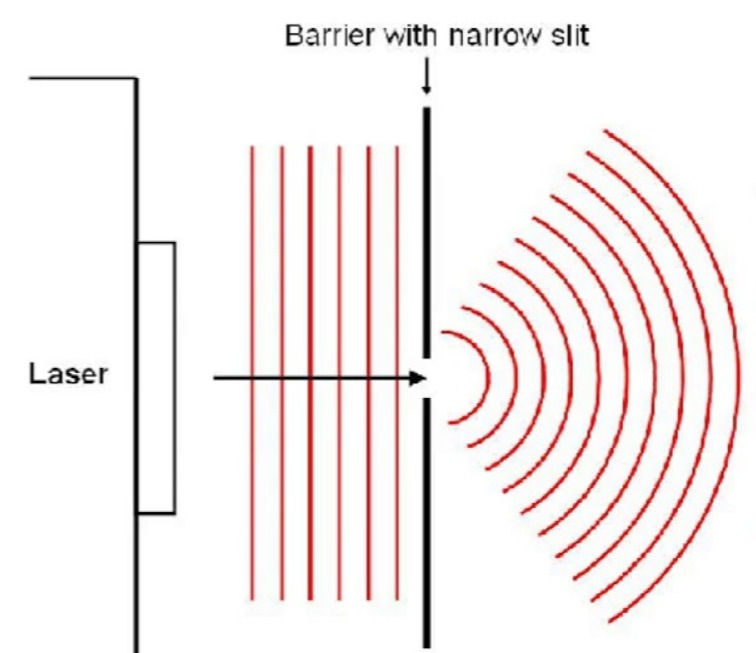
Now we get to the exciting bit - the actual physics. In order to understand the explanation, you must have a general idea of what diffraction is. A general explanation of diffraction is that it occurs when waves spread out after passing through a gap or round an obstacle. You can see this effect in a ripple tank when straight waves are directed at a gap. The narrower the gap, the more the waves will diffract (spread out). Moreover, the longer the wavelength, the more the waves will spread out also (we will show this mathematically afterwards).
As light waves reach each slit respectively, the light will diffract through the single slit. This diffraction pattern is similar to the ripples created when you throw a pebble into a pond. I have included an image of this below:
This pattern occurs from each individual slit, respectively. However, as the two slits are very close to each other (e.g. 0.1 mm), the two diffraction patterns will overlap creating a different, final diffraction (interference) pattern.
This all comes down to the principle of superposition which states that when two waves meet, the total displacement at a point is equal to the sum of the individual displacements at that point. This sounds complicated but is actually fairly straightforward. When two coherent waves overlap, at different points, they will either cancel out each other fully (destructive interference) or reinforce each other, creating an overall larger wave at that point (constructive interference). I have included an image below to help you visualise this better:


The phase of a vibrating particle at a certain time is the fraction of a cycle it has completed since the start of the cycle. The phase difference between two particles vibrating at the same frequency is the fraction of a cycle between the vibrations of the particles, measured either in degrees or radians: one cycle is 360 degrees or 2π radians. Therefore, if two waves (which have the same frequency and similar amplitudes) superpose, the positions of constructive and destructive interference will depend on the respective phase difference between the two waves. A phase difference of π radians (or 180 degrees) will result in complete destructive interference, as seen in Figure 1 above. A phase difference of 0 (or 2π) radians will result in complete constructive interference, as shown in Figure 2 above. So how does this relate to the 'Double Slit' experiment, you may ask? Well, this is where we start out derivation!
The Derivation
The bright and dark fringes correspond to a point of maximum constructive interference and maximum destructive interference between the two diffraction patterns. Thus, using what we have learnt previously, a bright fringe is formed when the two waves are in phase (a phase difference of 0 radians) and a dark fringe is formed when the two waves are out of phase (a phase difference of π radians). You may be wondering why this phase difference arising in the first place. This is due to what is known as the optical path length difference.

You see, if we take a point on the screen and label it X, two waves emitted, at the exact same time, from each respective slit (S1 and S2) will have to travel difference distances to reach that point on the screen. This difference in the distance travelled between the two waves is what is known as the optical path length difference. If this path difference is equal to the wavelength of the waves, say, λ, then the two waves will be in phase and will therefore constructively interfere, forming a bright fringe at that point on the screen. Likewise, if the path difference is half a wavelength, λ/2, the two waves will be out of phase (a phase difference of π radians) and will thus destructively interfere, forming a dark fringe at that point on the screen.
By this logic, constructive interference occurs at a point when the path difference between the two waves is equal to nλ (where n = 0, 1, 2, etc). In addition to this, destructive interference thus at a point when the optical path length difference is an integer number of half wavelengths, i.e. it is equal to (n + 0.5)*λ, where n = 0, 1, 2, etc. We can use this information, along with simple trigonometry and small-angle approximations, to derive a formula for the fringe spacing of the interference pattern (that is the distance between two consecutive bright [or dark] fringes).

The diagram above may look very complex, however it is quite simple once we break it down. As can be seen above, I have labelled the two slits, S1 and S2, with the distance between them labelled as s (this is known as the slit separation). Moreover, the distance from the slits to the screen is labelled as D. 'X', as aforementioned, is the position of the first bright fringe after the central one (which would occur at position 'O') and the distance between the two bright fringes is labelled as 'ω' - this is known as the fringe spacing. I have also put in two angles, θ, which are essentially identical. You may be wondering, how is this the case? What is the geometric rule for this to be true?
The answer lies in small-angle approximations (I have created a dedicated post on this, please check it out for a derivation of the following results which we will be using). Although it is not clear on the diagram (as, remember, it is not drawn to scale!), the distance, D, is much greater than the fringe spacing, ω. In other words, we can say that
D >> ω. Moreover, the slit separation, s, is also much greater than the path difference, ΔL; therefore, we can state that s >> ΔL. It is important to understand that, in this case, the path difference ΔL is simply equal to λ as there occurs constructive interference between the two waves, at point 'X', resulting in a bright fringe. In effect, for the second bright fringe, to the left or right of the central fringe, the path difference required for constructive interference will be 2λ, and so on. Thus, if you think about it, the angles labelled, θ, are going to be very small: the angles will be so small that we can use small-angle approximations. I will replace ΔL with nλ, just for conventional purposes, where 'n' refers to the 'number' of the bright fringe we are considering (e.g. the second or third bright fringe, to the left or right of the central fringe).
From here, we can just use trigonometry to derive the 'double-slit equation'. It should be apparent that s*sin(θ) is equal to nλ. Also, using trigonometry, one should be able to see that tan(θ) is equal to ω/D. From here, we can use our small-angle approximations which state that tan(θ) is approximately equal to θ and that sin(θ) is approximately equal to θ (these approximations are accurate to about 10 degrees). From this, we can thus find two equations in terms of θ and equate them. We can then rearrange the equation to have 'ω' as the subject (obviously you can use any variable but we commonly have ω as the subject of the equation) I have included an image of this below:

From here, n is normally set to 1 as the variable, ω, refers to the fringe spacing - this is the distance between two adjacent bright fringes. This gives us the final equation below:

Well that is the derivation finished! I hope you enjoyed that. We also coded a little simulation of this that I have included below (it may not function properly if you are using an Apple Mac). It allows you to alter the wavelength of the light incident on the slits, the distance from the slits to the screen, and the fringe separation. Notice and observe the effects that changing each variable has on the fringe spacing - it will be in accordance to our above equation. Like I said at the very beginning, the brightness (or intensity) of each fringe should theoretically be identical. However, as you will see in the simulation below, this is not the case. Without going into too much detail in this post, it due to the overlapping of the 'single slit effect'. Stay tuned, however, for a post on this when I derive the equation for the single slit diffraction experiment and then subsequently compare the diffraction pattern (and intensity) of the fringes. Thank you for reading!


Comments